Get Support
+44 (0) 7478 272574
-
By: admin
- 0 Comments
Removing the flywheel be sure to use a locking tool the nut should be very tight and often requires great effort to remove it. An air wrench often helps here and sometimes avoids the need for the locking tool. Be sure to tighten the nut very tightly on re-assembly. If it comes loose, both the flywheel and crankshaft may be damaged beyond repair.
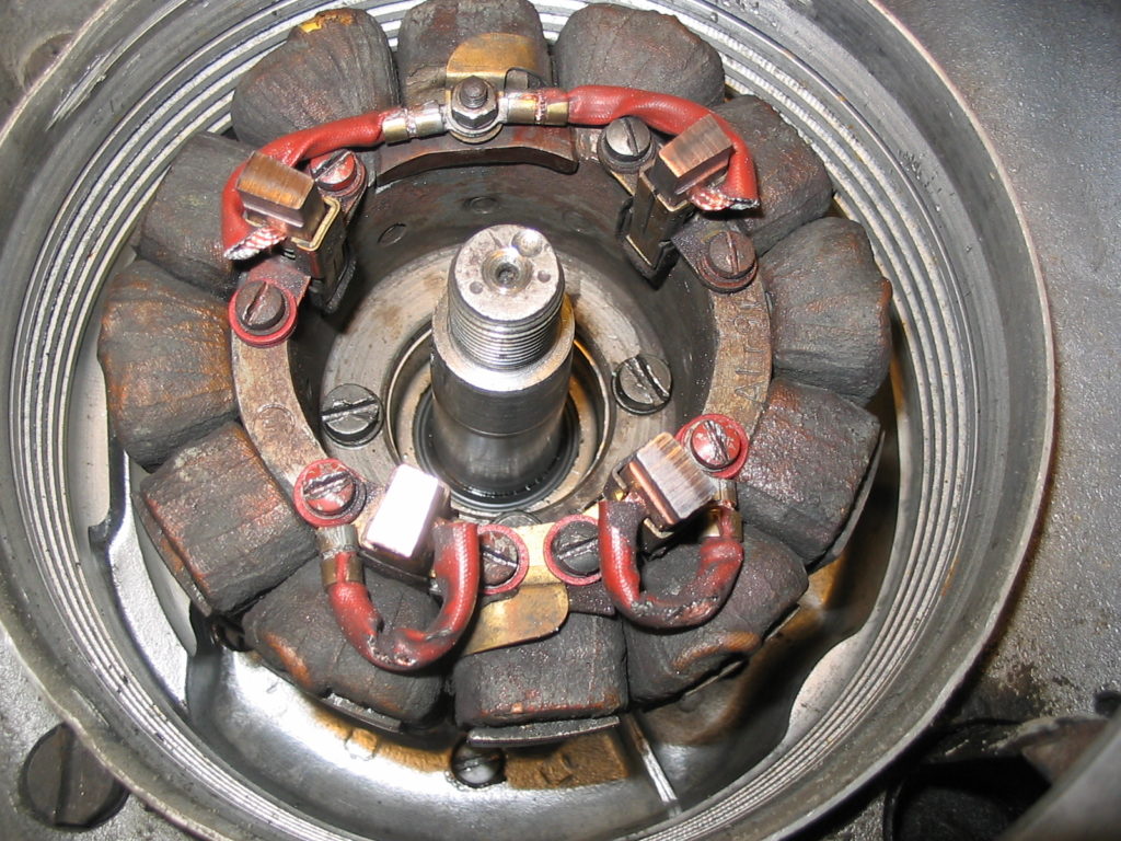
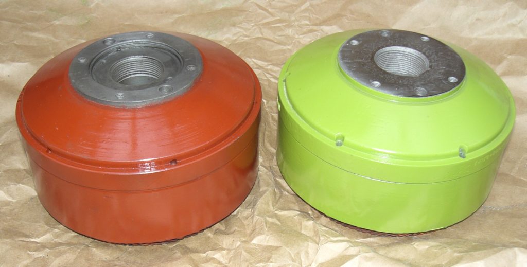
Siba dynastarts have a red oxide colour paint finish. Bosch units are finished in lime green paint. An extractor is needed to pull off the flywheel (Available from MOC Partsmart). You can identify the dynastart type by reference to the terminal tag numbers. (refer to Siba and Bosch black box systems and note the terminal numbers). The picture shows a Siba dynastart system fitted to all KR200 models up to chassis number 70643 ? reported date of introduction 6th April 1959.
Siba Units Fault: Pigtail routed around brush holder so that the cable is rubbing against the segment Insulation is worn through by friction on the rotating segment connecting wires ? when contact with the cable is made, the resulting short circuit damages both the armature and the stator.
Preventive action: As above, take care that the terminal is fastened to keep the cable close to the brush holder and without twisting.
Fault: Two of the brushes are connected to a terminal post between them and the pigtail can be too long or twisted, causing the cable to rub against the segment. Insulation is worn through by friction on the rotating segment connecting wires ? when contact with the cable is made, the resulting short circuit damages both the armature and the stator.
Preventive action: Ideally, the cable should be just long enough to reach the terminal post thus avoiding contact with the rotating segment connecting wires. If the cable is too long, it should be cut to length and a new terminal soldered or crimped on. Note the brush wire routing as shown in the above photograph.
Siba brush assembly with insulating bushes shown below:
This diagram shows a Bosch dynastart system fitted to all KR200 models from chassis number 70643 ? reported date of introduction 6th April 1959.
Bosch units
Pigtail routed around brush holder so that the cable is rubbing against outside of central hub. Insulation is worn through by friction on hub ? when contact with the cable is made, a dead short occurs that often destroys the armature connections to the commutator.
Preventive action: Fasten the terminal so that the cable is held closely to the brush holder while allowing the brush to move freely as it wears. (see attached diagram). Take care not to create a twist in the cable that may increase the chance of it contacting the commutator segment connection wires. These are 1.5mm thick varnish insulated copper wires.
2. Pigtail routed around brush holder so that the cable is rubbing against the segment Insulation is worn through by friction on the rotating segment connecting wires ? when contact with the cable is made, the resulting short circuit damages both the armature and the stator.
Preventive action: As above, take care that the terminal is fastened to keep the cable close to the brush holder and without twisting. Refer to the drawing above for brush wiring arrangement on BOSCH units.
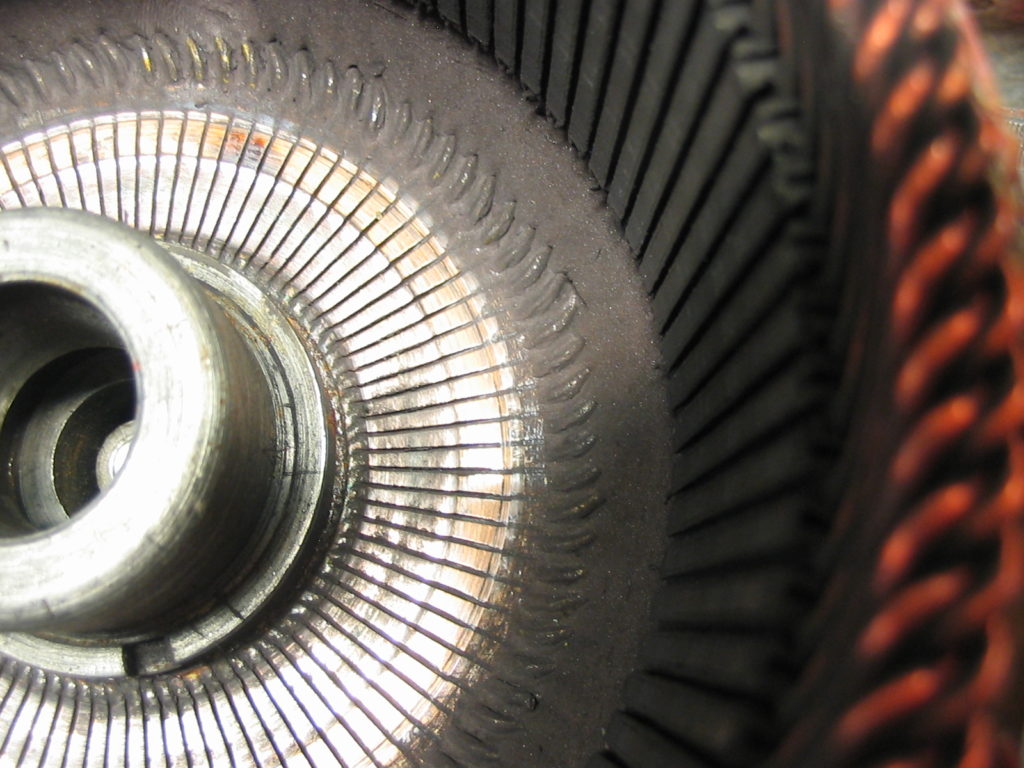
Note that the carbon brushes should be inspected frequently and certainly at each engine removal. If the brushes wear down to the connecting pigtails, and beyond, serious damage will occur to the commutator. In some cases, they can be restored by turning on a lathe but normally this can be done once only. In each case, the clearance must be restored between each commutator segment. If you do not understand any of the techniques involved, leave the servicing to a specialist. Dynastart components are hard to find on the used market and often extremely expensive. Look after yours and it will last the life of the car!
Service life of the brushes is dependant on the following factors:
- number and duration of starting operations
- Correct set-up of the carbon brushes
- Condition of the commutator, excessive wear on brush operating area
- Oil leaks from the main bearing seals. This can create short circuits from the carbon/oil paste that will burn out the unit
- Run-out and excessive end float on the crankshaft
- Total hours run of the engine
- Worn main bearings
Life of the brushes can be extended by avoiding use of the reversing feature. The reason for this is that the small lateral movement in the brushes causes them to wear with a slight taper on the operating face. When reverse operation is selected, the contact area is reduced and excessive wear can occur. This effect can be reduced by minimising the lateral movement in brush holder. Squeezing the holder sides in reduces the play. Of course, the brush must be able to move freely within the holder.
Below diagram shows the correct arrangement of insulating washers and bushes for Bosch dynastart brushes.
How to identify Bosch & Siba systems
Late in 1958, soon after FMR took over from RSM, a number of changes were made to the engines including a different crankshaft and dynastart system. If you have a Messerschmitt with FMR badges and vehicle identification number plate, then it was normally built with a BOSCH system. All cars with FMR diamond badges and plates were built with BOSCH electrical equipment. The U.K. has more BOSCH units than other countries because Messerschmitts were sold in here in greater numbers than other countries from 1959. Many have since had replacement engines from earlier cars and thus require identification of the dynastart for service work and repair parts. It should be noted that each type will function equally well in a car equipped with Bosch or Siba control boxes. There are only minor differences in the Black Box internal circuitry and these do not affect operation. Almost all terminal connections are dual marked for both systems ? you do not need to mark the cables before disconnection as each has the identifying code stamped on the rear of the terminal. Take care when replacing any worn or damaged terminal flags ? these are ?handed? left and right to avoid contact with the adjacent terminal post on the terminal block.
Removing the dynastart flywheel.
Do not attempt this job without the necessary holding tool for the flywheel unless an air wrench is available. Never try to stop rotation by jamming the fan blades (many have been ruined this way). The correct procedure is:-
1. Remove engine from the car and place on workbench. If you have a vice, clamp the front engine mounting plate in the vice jaws with the silencer taking the weight at the rear.
2. Remove the fan cover and fan.
3. Place the holding tool in the locating holes and slot in the outer casing (as shown in the manual.
4. If you do not have the holding tool, you can fabricate an anti rotation device from a strip of metal locating on the fan retaining screw holes. CAUTION: take great care not to fit longer screws into the fan retaining holes. If a screw is forced in too far, some of the commutator segments will be pushed out and the dynastart armature will be damaged beyond repair!
5. One alternative is to use an air operated power wrench when it is not normally necessary to use a locking device at all. (These wrenches are used in car tyre shops to remove wheel nuts. They exert great torque with a hammer blow action and will loosen the most stubborn nut without rotating the crankshaft).
6. After dismantling, clean everything as described in the manual. Replace brushes as required. Carefully inspect the key. If the key is loose and there is evidence that the flywheel/ armature has been moving on the shaft, you will need a replacement crankshaft. Note that the out of balance condition created by this fault is a major cause of low engine power output.
7. Inspect the keyway on the dyanastart flywheel bore. If there is evidence of movement, the same caution as above applies. (see note below about replacement flywheel hubs).
8. If all is well, carefully re-assemble ensuring the key is properly in place. Fit the spring washer before the crankshaft nut and tighten. Failure to tighten this nut sufficiently is a major cause of the damage described above. If you have a torque wrench, you can set it to 110Nm (81 il/ft). Alternatively, use an air wrench providing you are sure it is capable of maximum torque.
How to identify BOSCH and SIBA dynastart systems:-
BOSCH – The flywheel, (technically this is the armature), is painted a light green colour. A 5mm wide key is machined into the crankshaft to locate the flywheel and prevent it rotating on the crankshaft. The bore is machined to a taper of 7.5:1 to match the BOSCH type crankshaft. The internal diameter is slightly smaller than the SIBA unit, preventing use with a SIBA stator.
BOSCH stator or field coil assembly: Almost identical to the SIBA system but can be identified by the terminal connection markings on the main power leads: 92r, 92l, D+, 30h, & 31, Earlier SIBA codes (shown below) are also included on each terminal allowing connection to BOSCH or SIBA black box system. Brushes are smaller than SIBA and have different terminal size and geometry. Can be used with a SIBA flywheel and will fit a SIBA engine. Theoretically, performance will be slightly reduced because of the small increase in the air gap between flywheel and stator. In practice, these performance differences will not be noticed.
SIBA flywheels are painted light brown colour similar to red oxide primer. A 3mm wide key is machined into the crankshaft to locate the flywheel and prevent it rotating on the crankshaft. This key is a special rounded type and must not be replaced with a standard key. (Note that MOC exchange SIBA crankshafts have a standard type key). The bore is machined to a taper of 10:1 to match the SIBA type crankshaft. The internal diameter is slightly larger than the BOSCH unit, allowing use with a BOSCH stator.
SIBA – stator or field coil assembly: Almost identical to the BOSCH system but can be identified by the terminal connection markings on the main power leads: A,B1,B2, HE, M. Brushes are larger than BOSCH and have different terminal size and geometry. One pair of brushes is connected to a 4mm terminal stud post and fastened with a nut. Cannot be used with a BOSCH flywheel because the external diameter is too great.
How to identify BOSCH and SIBA black box control systems:-
The black box control system can be used with either type of dynastart system. BOSCH systems can be identified by the black cover on the votage regulator. Many BOSCH systems are worn out now and the contacts are flimsy and prone to failure and most have been replaced with the SIBA product from Partsmart. It is possible to replace a BOSCH regulator with a SIBA unit but the back plate must be drilled to accept the different hole centres and some cables will need to be extended. It is often more cost effective to buy a complete new box from Partsmart particularly as all the cables, regulator, and ignition coil are new.
New Dynastart hub assembly. These can be available separately (price on application), or your existing dynastart can be fitted with a new hub. This is a time consuming job requiring specialised equipment as each re-built assembly must be dynamically balanced to the original armature. It is normally only worth doing if the armature is in good condition and free of deep grooves in the commutator face. Note that this repair service is done in Germany and can take up to six months to complete. Cost varies according to the work involved but is typically around 130UKP. If your need is urgent, you will need to buy a new one as listed below.
1574 SIBA flywheel This is a complete new flywheel dynamically balanced and ready for use. Identified by light brown colour paint similar to red oxide primer and narrow keyway to suit SIBA crankshaft. Does not include stator or field coil assembly. Because of the heavy and fragile nature of this part, postage is extra at cost.
1575 BOSCH flywheel This is a complete new flywheel dynamically balanced and ready for use. Identified by yellow colour paint, (we could not find a match for the light green), and 5mm keyway to suit BOSCH crankshaft. Does not include stator or field coil assembly. Because of the heavy and fragile nature of this part, postage is extra at cost.
Repair of the stator or field coil assembly is a specialised job. If you feel you have the necessary skills, excellent repair and fault finding instructions, with pictures, are included in 1807 engine manual 5.50UKP from Partsmart. Alternatively, take this manual, with your defective stator to an electric motor repair shop.
Other useful publications are:
1821 Dynastart leaflet Siba
1822 Bosch Dynastart manual